

For simplifying a problem - we all assume certain things. After solving it successfully, we forget our initial assumptions - as if we had not assumed anything. This is where that certain problem becomes more complicated. At the end of the day, we forget the problem and standardise the solution. So that people always remember a solution and NOT the problem for which it's created...
The better cliche about the above thought is, when people wanted to write in the outer space where the gravity was very low- Americans invented a zero-gravity pen spending millions of dollars and years of time. The Russians proposed that we can use a lead-pencil.
Now we will come to the subject. we all know that power systems have a frequency of 50Hz (or 60 Hz) and say the transmission voltage is 33kV(or may be 66kV). We fix these variables quite nicely and forget about these when problems arise. After all they believed to be constant!
What if these variables are manipulated to gain advantage at the expense of consumers? why a utility might want to manipulate those?
For example, instead of keeping the system frequency at 50 Hz (keeping in mind the natural tolerance limits, for e.g. 49.5Hz ~ 50.5Hz), what if we can reduce the frequency intentionally, say to 47Hz? Here we assume that the under-frequency tripping of circuit breakers are below 47Hz so that we can keep the system running without tripping. at the same time we have manual controls so that we can adjust the speed governing so that it does not automatically settle at 50Hz.
What will be the effects of running the system at lower than 50Hz. As we all know that in most cases , a power system is inductive in load. Thus remembering the relationship Reactance X=L*w=L*2pi*f. This ends up in saying that if the system frequency is reduced- inductance will become lower in magnitude. Which means we can MANIPULATE the reactive power requirement. But the active energy supplied will not change.(no change in energy units)
This has additional effects in electrical apparatus of consumers as they are designed to operate in standard 50Hz frequency.
The same case is applicable to the line-line volatge. If we can manually reduce the line voltage of a 33kV line to about 32kV, what will happen. Surely we know that certain loads can not operate because of the voltage drop such as ACs, UPSs. but what can be gained from this manipulation. normally if the voltage of each generator is adjusted a bit lower than standard voltage, the power factor indicated in each generator will improve. This means that now each generator is supplying less reactive power requirement - and this in turn reduces the overall line voltage. This has implications in fuel efficiencies in case of a diesel generator. in case of hydro generators too this has certain FAVOURABLE effects to the operators of the power system.
Saturday, October 30, 2010
Saturday, July 24, 2010
The golden rule of power system operation
Say P - active power
Q - reactive power.
f - frequency
V - line voltage.
Then the golden rule is,
P is directly related with f.
Q is directly related with V.
Even certain experienced staff think that parameters such as line voltage depends on the active power produced and frequency may drop if there is not enough reactive power. This is Totally WRONG.
In other words,
If you are going to change the frequency of the supply you must increase the amount of fuel (eg. steam/diesel/HFO/waterflow) which in turn increases the prime-mover (eg. diesel engine/ gas turbine/ steam turbine/ hydro turbine) speed. But speed governors are meant to regulate this type of frequency variation and to maintain the speed of the prime mover.
If you are going to change the terminal voltage of the supply you must increase the excitation given to the alternator.
But keep in mind that the above are purely applicable to generators running isolated/islanded. Parallel operation and infinite grid operation are bit different and certain parameters can not be independently controlled (for eg. voltage in infinite grid).
If multiple generators are running in parallel, only by increasing the excitation of all generators - the voltage can be increased, and vice versa. If not, only the reactive power share will change, not the output voltage.
The other important aspect of operating a power system is to do with the power factor. People confuse with whether the power factor must lead or lag. There is another belief, improving the power factor means we try to make the 0.9 to 0.8 lagging. In almost every practical power system (there are few exceptions) , the power factor should be lagging, BUT not necessarily each and every generating set. In other words, even when the system power factor is lagging - one machine may be running with a leading power factor, at the expense of another.
Tuesday, July 13, 2010
A Bit of Automobile Technology
It would be nice to shift to a non-electrical topic for a change. A brief explanation would be provided about the recent past & current technology available in cars.
Different kinds of Transmission systems:
MT: Manual Transmission - The Coventional Gear selection system
AT: Automatic Transmission - The Automatic Gear selection system
ManuMatic/Tiptronic/GearTronic: Manu(al + Auto)matic system
CVT: Continuously Variable Transmission
Above the letters indicate the following:
1. P - Park
2. R - Reverse
3. N - Neutral
4. D - Drive
5. 2 - Second gear is maximum
6. L - Low/1st gear is maximum
Normally manual transmission employs a clutch but an auto transmission utilises a torque converter instead of clutch.
Few emission control systems:
CVCC: Compound Vortex Controlled Combustion by Honda for complying with emission standards
CC: Catalytic Converter used for treating toxic emissioons
Various ValveTrain systems:
VTEC: Variable Valve Timing and Lift Electronic Control by Honda
VVT-i : Variable Valve Timing with Intelligence developed by Toyota
SOHC: Single Over Head Camshaft system
DOHC: Double Over Head Camshaft system

Multiple Fuel delivery systems:
Carburettor:Conventional indirect injection
MFI: Mechanical Fuel Injection
EFI: Electronic Fuel Injection
Engine Efficiency Improvement systems:
Intercooler/Aftercooler:
Turbocharger/TurboSupercharger:
Passenger Safety systems:
ABS: AntiLock Braking System
EBD: Electronic Brakeforce Distribution
Emerging Aotomobile Design technologies:
HEV: Hybrid Electric Vehicle cosists of an IC Engine and Electric motors
Different kinds of Transmission systems:
MT: Manual Transmission - The Coventional Gear selection system
AT: Automatic Transmission - The Automatic Gear selection system
ManuMatic/Tiptronic/GearTronic: Manu(al + Auto)matic system
CVT: Continuously Variable Transmission
Above the letters indicate the following:
1. P - Park
2. R - Reverse
3. N - Neutral
4. D - Drive
5. 2 - Second gear is maximum
6. L - Low/1st gear is maximum

Normally manual transmission employs a clutch but an auto transmission utilises a torque converter instead of clutch.
Few emission control systems:
CVCC: Compound Vortex Controlled Combustion by Honda for complying with emission standards
CC: Catalytic Converter used for treating toxic emissioons

Various ValveTrain systems:

VTEC: Variable Valve Timing and Lift Electronic Control by Honda
VVT-i : Variable Valve Timing with Intelligence developed by Toyota
SOHC: Single Over Head Camshaft system
DOHC: Double Over Head Camshaft system

Multiple Fuel delivery systems:
Carburettor:Conventional indirect injection
MFI: Mechanical Fuel Injection
EFI: Electronic Fuel Injection
Engine Efficiency Improvement systems:
Intercooler/Aftercooler:
Turbocharger/TurboSupercharger:


Passenger Safety systems:
ABS: AntiLock Braking System
EBD: Electronic Brakeforce Distribution
Emerging Aotomobile Design technologies:
HEV: Hybrid Electric Vehicle cosists of an IC Engine and Electric motors


Monday, June 28, 2010
Half-a-loaf of Automotive Aerodynamics (AA)
what is aerodynamics?
Aerodynamics is a branch of dynamics concerned with studying the motion of air, particularly when it interacts with a moving object as defined by wikipedia.
Aerodynamics of automobiles:
drag:
drag is a fluid dynamics term, sometimes called as air resistance or fluid resistance. It is defined as "forces that oppose the relative motion of an object through a fluid. Drag forces act in a direction opposite to the oncoming flow velocity". (wikipedia)

lift:
A fluid flowing past the surface of a body exerts a surface force on it. Lift is defined to be the component of this force that is perpendicular to the oncoming flow direction. It contrasts with the drag force, which is defined to be the component of the surface force parallel to the flow direction.(wikipedia)

Note: In aircrafts Lift/drag ratio is expected to be higher. But this is not the case in automobiles where lift is to be reduced and drag too to be reduced. What is especially required in an autombile such as a racing car is the downforce (as opposed to the lift required in aircrafts).

Upper: non-aerodynamic car; Lower: aerodynamically improved design
From: http://www.generalamherst.com
A diffuser is seen in most racing cars:

Rear diffuser of Porsche - Courtesy: Wikipedia

Rear spoiler of Toyota - Courtesy: Wikipedia

Front Air Dam of Mazda - Courtesy: Mazda
Please visit hotrod for a fine detailed description of the role of aerodynamics in automobiles!
Aerodynamics is a branch of dynamics concerned with studying the motion of air, particularly when it interacts with a moving object as defined by wikipedia.
Aerodynamics of automobiles:
drag:
drag is a fluid dynamics term, sometimes called as air resistance or fluid resistance. It is defined as "forces that oppose the relative motion of an object through a fluid. Drag forces act in a direction opposite to the oncoming flow velocity". (wikipedia)
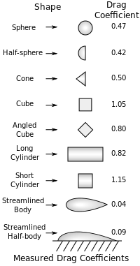
| Shape and flow | Form drag | Skin friction |
|---|---|---|
| 0% | 100% | |
| ~10% | ~90% | |
 | ~90% | ~10% |
 | 100% | 0% |
lift:
A fluid flowing past the surface of a body exerts a surface force on it. Lift is defined to be the component of this force that is perpendicular to the oncoming flow direction. It contrasts with the drag force, which is defined to be the component of the surface force parallel to the flow direction.(wikipedia)

Note: In aircrafts Lift/drag ratio is expected to be higher. But this is not the case in automobiles where lift is to be reduced and drag too to be reduced. What is especially required in an autombile such as a racing car is the downforce (as opposed to the lift required in aircrafts).

Upper: non-aerodynamic car; Lower: aerodynamically improved design
From: http://www.generalamherst.com
A diffuser is seen in most racing cars:

Rear diffuser of Porsche - Courtesy: Wikipedia

Rear spoiler of Toyota - Courtesy: Wikipedia

Front Air Dam of Mazda - Courtesy: Mazda
Please visit hotrod for a fine detailed description of the role of aerodynamics in automobiles!
Friday, May 28, 2010
Non-Conventional Renewable Energy (NCRE)
The term renewable energy now has become a magical word in energy. The world is constantly changing and so is the power sector. Nowadays people talk about 'deviating' from the 'conventional' energy sources such as thermal, hydro, nuclear etc and magically spell wind, solar, biomass, wave, tidal, geothermal, and so on.
Are those viable and financially feasible? what about the technical feasibility - such as reliability, stability issues?
Wind energy:
Wind takes the first priority when it comes to non-conventioanl renewable energy source. Though it is unrelaible at times, may have stability issues, voltage problems, might need reactive power compensation. Still it is CLEAN, Not forgetting that it needs a very high initial investment in comparative terms. Remember that open cycle gas turbines are the opposite. Their capital cost is in the lower limits in any commercial scale power systems.

A Horizontal axis wind turbine generator: from Howstuffworks
Solar Energy:
Solar PV
Solar energy is said to be abundant, though the fabrication of these photovoltaic semiconductors are not so easy. their Cost/Wattage is significantly high and the average payback period is well beyond 10 years.
Solar thermal
Biomass Energy:
Wave/Tide Energy:
Are those viable and financially feasible? what about the technical feasibility - such as reliability, stability issues?
Wind energy:
Wind takes the first priority when it comes to non-conventioanl renewable energy source. Though it is unrelaible at times, may have stability issues, voltage problems, might need reactive power compensation. Still it is CLEAN, Not forgetting that it needs a very high initial investment in comparative terms. Remember that open cycle gas turbines are the opposite. Their capital cost is in the lower limits in any commercial scale power systems.

Solar Energy:

Solar PV
Solar energy is said to be abundant, though the fabrication of these photovoltaic semiconductors are not so easy. their Cost/Wattage is significantly high and the average payback period is well beyond 10 years.

Solar thermal

Biomass Energy:
Wave/Tide Energy:
Industrial Automation
Industrial Automation is not a totally new concept. It has been practised in the industry for a long time. But the introduction of personal computers has revolutionised the automation industry providing easy access, custom software applications and so on.
Automation is a process where sensors/transducers are employed to 'sense' the signal, one or more controllers 'guiding' the operation involved and the desired output is achieved in the form of actuators/motors/physical parameters such as temperature/pH in a factory.
Sensors:
Pressure sensors
Position transducers
Proximity sensors
Temperature sensors
Humidity sensors
These sensors measure the relative humidity by converting the signals to desired voltage/current output.
Level sensors
Used to measure the level, for e.g. water level in a tank/ chemical level in a container.
Load cells
These are utilised to measure the weight in electronic form.
Inputs:
Analog input
4-20mA current input
0-10V voltage input
Digital inputs
push buttons
Controllers:
Process indicators
Timers
Counters
Temperature controllers - PID
PC-based controllers
Input-output modules
Programmable logic controllers (PLC): AC/DC inputs & outputs
Variable speed drives (VSD)/ Variable frequency drives (VFD)
Converters:
Converters are used to change the signal type from one to another. This conversion may take a form of analog signals to digital signals (ADC) or changing the signal medium such as RS232 serial type to RS485 two-wire type.
Actuators:
Based on the controller output, actuators would perform the desired action to change the controlled variable. These are mostly motion-oriented, for e.g. motors, solenoid valves, electromagnetic relays etc.
- Solenoid valves (electrically controlled valves)
- Motors such as steppers, servos, permanent magnet types
- Voltage-controlled electromagnetic relays
Software:
Automation configuration software (between h/w and s/w)
Automation display software ( to display the controlled parameters)
Supervisory control & Data acquisition (SCADA)
Automation is a process where sensors/transducers are employed to 'sense' the signal, one or more controllers 'guiding' the operation involved and the desired output is achieved in the form of actuators/motors/physical parameters such as temperature/pH in a factory.
Sensors:
Pressure sensors
Position transducers
- linear
- rotary

Proximity sensors
- capacitive proximity sensors
- inductive proximity sensors
- photoelectric proximity sensors


Temperature sensors
- Resistance Temperature Device (RTD)
- Thermocouple (TC)
- Thermistors

Humidity sensors
These sensors measure the relative humidity by converting the signals to desired voltage/current output.
Level sensors
Used to measure the level, for e.g. water level in a tank/ chemical level in a container.
Load cells
These are utilised to measure the weight in electronic form.
Inputs:
Analog input
4-20mA current input
0-10V voltage input
Digital inputs
push buttons
Controllers:
Process indicators
Timers
Counters
Temperature controllers - PID
PC-based controllers
Input-output modules
Programmable logic controllers (PLC): AC/DC inputs & outputs
Variable speed drives (VSD)/ Variable frequency drives (VFD)


Converters:
Converters are used to change the signal type from one to another. This conversion may take a form of analog signals to digital signals (ADC) or changing the signal medium such as RS232 serial type to RS485 two-wire type.

Actuators:
Based on the controller output, actuators would perform the desired action to change the controlled variable. These are mostly motion-oriented, for e.g. motors, solenoid valves, electromagnetic relays etc.
- Solenoid valves (electrically controlled valves)
- Motors such as steppers, servos, permanent magnet types
- Voltage-controlled electromagnetic relays

Software:
Automation configuration software (between h/w and s/w)
Automation display software ( to display the controlled parameters)
Supervisory control & Data acquisition (SCADA)

Sunday, May 16, 2010
Power Electronics
power semiconductor devices are as follows:
A p-n junction is the basic building block of a semiconductor. p indicates positive charges and n indicates negative charges.
Zener diode is a special diode which is utilised in the reverse-biased mode in voltage regulating apllications.
Schottky diode has very low forward voltage drop but at the same time weak reverse bias withstand capability.
High Amp power diodes are type of p-n jucntion diodes designed to handle high currnet with proper heat dissipation and easy mounting arrangements.
Rectificaion of AC to DC wave can be performed by diodes. A single diode can rectifiy half of an AC waveform, but a full bridge rectifier which contains 4 diodes in a special arrangement can result in fully-rectified DC waveform.
Transistors:
Bipolar transistors can be either pnp transistor or npn transistor.
In operation they employ both polarities of charges (i.e. electrons and holes) so the name bi-polar transistors. These are the conventional transistors.
A transistor can be used in a circuit as a switch which turns ON or OFF in specific conditions, or, as an amplifier which amplifies the signal fed into the transistor. Other evolutions of bipolar transistors are IGBTs, FETs, MOSFETs which have certain advantages depending on the application for which it is used for. For e.g. some of the above are fast-switching.
Thyristors :
Firing angle is the main aspect in the operation of a thyristor. A thyristor will start to conduct when a certain threshold current flows through its secondary circuit. These are mostly applied in high current switching.
HVDC -
Not forgetting the historical fact that there was an AC/DC war between Westinghouse & Edison , AC became predominant in transmitting power to long distances due to the inherent features of AC. Saying that, nowadays for ultra-long distance power transmission DC has been found more beneficial than AC. HVDC refers to high voltage direct current (dc) system. As the power generation is easy in AC form, in this HVDC system, it is then inverted into DC, transmitted over very long distance, and then converted back to conventional AC.
AC power--->Converter--->DC transmission line--->Inverter---->AC power
Here comes the ultimate importance of REAL high current low loss Power Electronic Converters and Inverters.

A 2000A 250 kV high voltage direct current (HVDC) thyristor valve rated 2000 A,250 kV dc at Manitoba Hydro's Henday converter station: Source unknown
FACTS -
Flexible alternating current (ac) transmission system is defined by the IEEE as "a power electronic based system and other static equipment that provide control of one or more AC transmission system parameters to enhance controllability and increase power transfer capability."
To summarise the confusing AC/DC below provided is an application example.
1. AC to DC: rectifiers e.g. full bridge rectifier
2. DC to AC: inverters e.g. UPS in battery mode
3. AC to AC: transformers e.g. a 33/11kV power transformer
4. DC to DC: switching/chopping e.g. switch mode power supply
- p-n junction diode - conventional semiconductor-semiconductor junction diode
- schottky diode - faster switching, low forward voltage drop diode
- bipolar junction transistor (BJT) - conventional where both polarity charges operate (electrons & holes)
- field effect transistor (FET) - a unipolar transistor
- metal oxide semiconductor FET (MOSFET)
- Insulated gate bipolar transistor (IGBT)
- silicon controlled rectifier (SCR)
- triode for AC (TRIAC) - a bidirectional thyristor
A p-n junction is the basic building block of a semiconductor. p indicates positive charges and n indicates negative charges.
Zener diode is a special diode which is utilised in the reverse-biased mode in voltage regulating apllications.
Schottky diode has very low forward voltage drop but at the same time weak reverse bias withstand capability.
High Amp power diodes are type of p-n jucntion diodes designed to handle high currnet with proper heat dissipation and easy mounting arrangements.
Rectificaion of AC to DC wave can be performed by diodes. A single diode can rectifiy half of an AC waveform, but a full bridge rectifier which contains 4 diodes in a special arrangement can result in fully-rectified DC waveform.

Transistors:
Bipolar transistors can be either pnp transistor or npn transistor.
In operation they employ both polarities of charges (i.e. electrons and holes) so the name bi-polar transistors. These are the conventional transistors.
A transistor can be used in a circuit as a switch which turns ON or OFF in specific conditions, or, as an amplifier which amplifies the signal fed into the transistor. Other evolutions of bipolar transistors are IGBTs, FETs, MOSFETs which have certain advantages depending on the application for which it is used for. For e.g. some of the above are fast-switching.

Thyristors :
Firing angle is the main aspect in the operation of a thyristor. A thyristor will start to conduct when a certain threshold current flows through its secondary circuit. These are mostly applied in high current switching.

HVDC -
Not forgetting the historical fact that there was an AC/DC war between Westinghouse & Edison , AC became predominant in transmitting power to long distances due to the inherent features of AC. Saying that, nowadays for ultra-long distance power transmission DC has been found more beneficial than AC. HVDC refers to high voltage direct current (dc) system. As the power generation is easy in AC form, in this HVDC system, it is then inverted into DC, transmitted over very long distance, and then converted back to conventional AC.
AC power--->Converter--->DC transmission line--->Inverter---->AC power
Here comes the ultimate importance of REAL high current low loss Power Electronic Converters and Inverters.

A 2000A 250 kV high voltage direct current (HVDC) thyristor valve rated 2000 A,250 kV dc at Manitoba Hydro's Henday converter station: Source unknown
FACTS -
Flexible alternating current (ac) transmission system is defined by the IEEE as "a power electronic based system and other static equipment that provide control of one or more AC transmission system parameters to enhance controllability and increase power transfer capability."
To summarise the confusing AC/DC below provided is an application example.
1. AC to DC: rectifiers e.g. full bridge rectifier
2. DC to AC: inverters e.g. UPS in battery mode
3. AC to AC: transformers e.g. a 33/11kV power transformer
4. DC to DC: switching/chopping e.g. switch mode power supply
Internal Combustion (IC) Engines
Internal combustion engines have been a compact method to drive a generator to produce mechanical energy. IC engines can be mainly classified into two.
1. Diesel engines (Compression-ignition)
2. Petrol/gasoline engines (Spark-ignition)
Diesel and Gasoline engines are reprocating engines too as 1/more pistons move laterally to generate rotational energy which in turn used as a prime mover for either generators or simply as marine engines to drive the propeller.
The injection of fuel (either diesel or gasoline) can be direct or indirect.
4-stroke cycle:
Main Parts of a diesel generator set:
1. Diesel engines (Compression-ignition)
2. Petrol/gasoline engines (Spark-ignition)
Diesel and Gasoline engines are reprocating engines too as 1/more pistons move laterally to generate rotational energy which in turn used as a prime mover for either generators or simply as marine engines to drive the propeller.

The injection of fuel (either diesel or gasoline) can be direct or indirect.
- Direct injection is done by the help of specially designed fuel injectors. This is applicable mostly to diesel engines.
- Indirect injection is where fuel is not directly INJECTED. Actually this suits to gasoline engines. A carburrettor helps to DRAW the fuel rather than injecting it to the engine.This is applicable mostly to petrol engines. In modern cars, a carburettor is replaced by ELECTRONIC FUEL INJECTION (EFI), where injection is controlled by electronic means normally by a dedicated controller.
4-stroke cycle:
- Intake stroke
- Compression stroke
- Power stroke
- Exhaust stroke

Main Parts of a diesel generator set:

Mechanical components:
- cylinder liner
- piston
- connecting rod
- crankshaft
- camshaft
- push rod
- valve spring
- air inlet valve
- exhaust valve
- injector nozzle
- fuel pump
- ac pump
- fuel filter
- oil filter
- air filter
- oil sump
- fuel tank
- flywheel
- rocker arm
- governor

- starting motor
- battery
- charging alternator
- gen stator
- gen rotor
- windings
- MVR/ AVR/ DVR
- DC generator/PM Generator - exciter
- rotating diode set
- oil pressure sensor
- water temperature sensor
- speed sensor
- gen control panel (GCP)
- gen circuit breaker (GCB)
Power Quality
Is there an international quality standard ISO 100001 for Quality of Power? Not yet. But quality of the important parameters of Power, namely, continuity of service, frequency, voltage, sinusoidal waveshape are to be within acceptable limits.
Continuity of Power:
Voltage variations:
Other notable power quality issues:

Continuity of Power:
- momentory interruption (caused by transient faults)
- temporary interruption (a bird getting burnt)
- outage (sustained faults in Line/Station)
- blackout (outage in a wider area, might take days to weeks to recover)
Voltage variations:
- voltage dip/sag (momentary): rms voltage is below the nominal voltage - but within 10% drop
- voltage swell: rms voltage is above the nominal voltage - but within 10% limit
- flickering : rms voltage goes above & below the nominal repetitively in lights - but within 10% variation
- undervoltage : rms voltage drop is below 10% of nominal voltage
- brownout: term similar to undervoltage
Other notable power quality issues:
- Under-frquency/ over-frequency
- Harmonics - Total harmonic distortion (waveshape distortion caused by non-linear loads such as SMPS and CFLs)
- Transients (by switching, lightning or network faults)

Friday, February 26, 2010
High Voltage (HV) Engineering
Why are power engineers interested in Very High Voltages? Can't they do it in low voltage?
According to the Ohm's theorem;
Power loss in a conductor, P' = I^2 * R
=> So the power loss is directly proportional to the square of the line current.
=> Therefore to reduce losses, 'I' should be minimised.
But,
The Power requirement is fixed. Then by looking at the equation -
Apparent power, P = V * I
=> To minimise I;
=>V should be maximised.
That leads to the conclusion that transmission voltage should be increased to the MAXIMUM possible value.
Can we do that?
Even if we produce a three phase voltage of 1,000,000,000 V for argument's sake, can our equipments withstand it?
starting from the power cable of transformers, transformer terminals, power conductors, line towers, insulators, switchgear, and numerous things in a line SHOULD be made to withstand that same 1,000,000,000 V - Which is nearly impossible in present conditions.
So it boils down to simply an issue of trade-off.
=> bigger the voltage better; smaller the current better. for that it means a VERY big investment. So let us reduce some voltage. Then the current flow is going to increase. So as the line losses!
Three types of matter:
As matter is present in 3 kinds, so as the electrical insulation is of following types:
1. Solid
2. Liquid
3. Gas
HV breakdown:
High voltage naturally consists of an electric field pattern, and it depends on the voltage. It implies that certain insulation is capable of catering a certain maximum voltage. Beyond that, it will exhibit signs of leakage. That may sometimes lead to complete breakdown of that insulation medium. This value for still air is about 30 kV per cm.
HV insulators are of special design in order to create a longer creepage path. This avoids flashovers to some extent. But when dust particles and particulate matter get deposited on the insulator surface, and when rain water falls on that dirty surface, flashovers become frequent. Proper maintenanance of Hv insulators are thus essential for power quality.
Corona:
We can say corona is a phenomenon which occurs near a HV conductor. This effect may have been observed by many people residing under HV lines and especially near line supports.
An electrical field (stress) will be present around any electrical conductor. In HV conductors, the field strength would be higher. When this value increases beyond a certian limit, it starts to ionise the sorrounding air molecules. When sufficient ions are formed around that line, a portion of air becomes conductive (or called leakage). This is called 'corona effect'.
Corona has the following features, which are clearly visible in night time.
1. Hissing sound
2. Bluish/violet glow
This certainly means there is a power loss due to corona effect.
It should be noted that the electrical field strength will become more in bent/sharp conductors. Near the pole supports conductors need to bent for spur connections/ tensioning. That's why we observe corona near pole supports.
Terms associated with corona voltages are:
-corona inception voltage
-disruptive critical voltage
According to the Ohm's theorem;
Power loss in a conductor, P' = I^2 * R
=> So the power loss is directly proportional to the square of the line current.
=> Therefore to reduce losses, 'I' should be minimised.
But,
The Power requirement is fixed. Then by looking at the equation -
Apparent power, P = V * I
=> To minimise I;
=>V should be maximised.
That leads to the conclusion that transmission voltage should be increased to the MAXIMUM possible value.
Can we do that?
Even if we produce a three phase voltage of 1,000,000,000 V for argument's sake, can our equipments withstand it?
starting from the power cable of transformers, transformer terminals, power conductors, line towers, insulators, switchgear, and numerous things in a line SHOULD be made to withstand that same 1,000,000,000 V - Which is nearly impossible in present conditions.
So it boils down to simply an issue of trade-off.
=> bigger the voltage better; smaller the current better. for that it means a VERY big investment. So let us reduce some voltage. Then the current flow is going to increase. So as the line losses!
Three types of matter:
As matter is present in 3 kinds, so as the electrical insulation is of following types:
1. Solid
2. Liquid
3. Gas
HV breakdown:
High voltage naturally consists of an electric field pattern, and it depends on the voltage. It implies that certain insulation is capable of catering a certain maximum voltage. Beyond that, it will exhibit signs of leakage. That may sometimes lead to complete breakdown of that insulation medium. This value for still air is about 30 kV per cm.

HV insulators are of special design in order to create a longer creepage path. This avoids flashovers to some extent. But when dust particles and particulate matter get deposited on the insulator surface, and when rain water falls on that dirty surface, flashovers become frequent. Proper maintenanance of Hv insulators are thus essential for power quality.

Corona:
We can say corona is a phenomenon which occurs near a HV conductor. This effect may have been observed by many people residing under HV lines and especially near line supports.
An electrical field (stress) will be present around any electrical conductor. In HV conductors, the field strength would be higher. When this value increases beyond a certian limit, it starts to ionise the sorrounding air molecules. When sufficient ions are formed around that line, a portion of air becomes conductive (or called leakage). This is called 'corona effect'.

Corona has the following features, which are clearly visible in night time.
1. Hissing sound
2. Bluish/violet glow
This certainly means there is a power loss due to corona effect.
It should be noted that the electrical field strength will become more in bent/sharp conductors. Near the pole supports conductors need to bent for spur connections/ tensioning. That's why we observe corona near pole supports.
Terms associated with corona voltages are:
-corona inception voltage
-disruptive critical voltage
Thursday, February 25, 2010
Design of Electrical Installations
Lighting/ Illumination:
Types of light fixtures-
1. Incandescent lamps
2. Fluorescent lamps
3. Compact fluorescent lamps
4. Halogen lamps
5. High pressure mercury vapour lamps
6. Metal Halide lamps
6. Low pressure Sodium vapour lamps
7. Neon indicator lamps
-Illumination level unit - Lux, Recommended lighting levels
-Color temperature - Warm white, cool white, daylight white
-Color rendering
-Ambient lighting & task lighting
-Illumination Simulation tools, e.g. Dialux
Power outlets/sockets:
Ratings - 5A, 13A, 15A
Terminals: L, N, E
Routing of power conductors:
1. Cable trench
2. Cable tray
3. Cable ladder
4. Cable duct
5. Cable trunking
Airconditioning & Ventilation:
1. Exhaust fans
2. Split type AC (Indoor & outdoor unit)
3. Package type AC
4. ACCU
5. PACU
6. AHU
Lightning protection and Earthing:
1. Earth rods
2. Earthing tape
3. Down conductors
4. No of Earthing points
4. Dry chemical powder
Types of light fixtures-
1. Incandescent lamps
2. Fluorescent lamps
3. Compact fluorescent lamps
4. Halogen lamps
5. High pressure mercury vapour lamps
6. Metal Halide lamps
6. Low pressure Sodium vapour lamps
7. Neon indicator lamps

-Illumination level unit - Lux, Recommended lighting levels
-Color temperature - Warm white, cool white, daylight white
-Color rendering
-Ambient lighting & task lighting
-Illumination Simulation tools, e.g. Dialux

Power outlets/sockets:
Ratings - 5A, 13A, 15A

Terminals: L, N, E
Routing of power conductors:
1. Cable trench

2. Cable tray
3. Cable ladder

4. Cable duct
5. Cable trunking

Airconditioning & Ventilation:
1. Exhaust fans
2. Split type AC (Indoor & outdoor unit)
3. Package type AC
4. ACCU
5. PACU
6. AHU
Lightning protection and Earthing:
1. Earth rods
2. Earthing tape
3. Down conductors
4. No of Earthing points

Telecommunication:
1. Internet
2. Telephone

3. IP TV
4. PABX
5. Satellite TV
Fire protection:
Types of Fire-
1. Paper/cloth/wood etc
2. Flammable liquids
3. Flammable gases
4. Electrical faults

Types of Extinguishers:
1. Water
2. Foam
3. CO2

4. Dry chemical powder
5. Wet chemical powder
6. Sand buckets
Fire detection:
1. Heat detectors
2. Smoke detectors - Infrared
3. Smoke detectors - Photoelectric

4. Duct detectors
5. Manual call points
6. Emergency fire exit and gathering (meeting) points
