Electricity is a form of energy, at the same time, a power source. It is an energy source when it is captured for a length of time and a power source when it is seen in a momentary time (instantaneous).
Normally electricity is produced where a
form of energy is converted into another form of energy.
eg: 1. Chemical energy -> Electrical energy : Wet and dry cell batteries
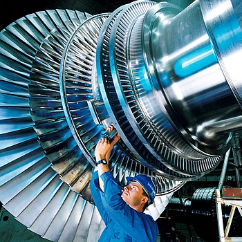
2. Mechanical energy -> Electrical energy : Turbine generators
3. Light energy -> Electrical energy : Solar Photovoltaic panels
In another point of view, there are lot of
methods electricity is produced in commercial scale. those are,
- Steam power plants
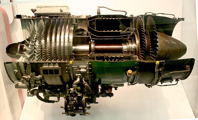
- Gas power plants
- Diesel power plants
- Bio mass power plants
- Geo thermal power plants
- Solar power plants
- Wind power plants
- Nuclear power plants
etc.
For a long time, electricty was seen as flow of positive energy particles through a completed circuit. But later it was found out that it is the '
free electrons' which contribute to the flow of 'charges'. That is why conventinally current is denoted in the direction of + to - in a 1.5 V dry cell battery - whereas the electrons flow in the opposite direction.
(note that flow of negatively charged particles ASSOCIATED with the imaginary flow of positive paticles called 'holes' is the true representation of the electricity)
Electrical parameters - Unit
1. Voltage difference - Volts
2. Current -Amperes
3. Power - Watts*
* there are other units as well, with different meanings- of electrical power.
A perfect analogy of current flowing in a conductor is, similar to water flowing in a sland (sloped) pipe,
Where the waterflow is like the electric current; voltage difference is like the slope of pipe and the electric power is the work done on flowing water per unit time.
When electric current is flowing in a conductor, it creates
magnetic field lines along the conductor. When a voltage is present in a node (a point), it creates
electric field lines around that node. Theoretically speaking, electromagnetic wave is made up of electric and magnetic fields which are perpedicular- propagating in a direction under certain circumstances. But a simple study of basic electricity is different from the complex study and mathematics of this field interaction in an electromagnetic wave. so this topic will not be discussed here now.
When considering the
electrical conductivity of materials, common materials are devided into 3 categories.
1. conductors* (copper, aluminium, gold, carbon rod etc)
2. insulators (mica, poly-ethene, plastics, porcelain etc)
3. semi-conductors (doped silicon, doped germanium)
* At present, there is a further classification of '
super conductors'. Some special materials - in extreme circumstances like very low temperature have superconductivity; a state where electrical resistance is almost negligible. This has again wonderful applications (like semi conductors) in the field, for eg., superconductivity is used to obatain ultra high powerful electro-magnets used in electric trains.
Note that
pure Silicon is an insulator. They become semi-conductors if they are doped with other elements like Boron or phosporous. These materials are of utmost importance in the electronics industry and revolutionised the world by the discovery of 'Semiconductor Transistors' in the Bell laboratories.
Current in a circuit can be
direct or alternating. It is called direct (dc) when the polarity or direction of the current does not change with time.It is called alternating (ac) when the polarity does change with time in a definite manner such as changing 50 times per second. This leads to the 50 Hz electrical supply. In most parts of Americas, the supply will change it's polarity 60 times (60 Hz).
An ac supply can be of
single phase (2/3 wires) or
polyphased. The most popular polyphase power system is three-phase(3/4 wires) electricity supply. A three phase system is more economical than seperate single phase systems.
In a utility's (power company) point of view, a
power system is seen in three major steps;
1. Power generation
2. Power transmission
3. Power distribution.
In a consumers point of view, a power system is seen as '
Power utilisation', which includes supply reliability, supply quality and energy efficiency.
The
domestic power supply (in Sri Lanka) has the following characteristics.
1. Supply voltage is at 230 V ac
2. The incoming supply has two ac terminals: Live and Neutral wires
3. In addition, there is a ground/earth wire installed in the home premises.
4. Supply frequency is 50 Hz.
The major
electrical machines involved in a power system are,
1. Generators
2. Motors
3. Transformers
Generators are further classified into ac, dc generators; while motors are classified into synchronous, asynchronous motors; And transformers can be classified into step up, step down transformers.


